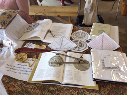
Another astrolabe in work

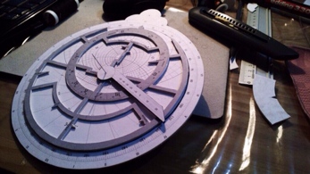
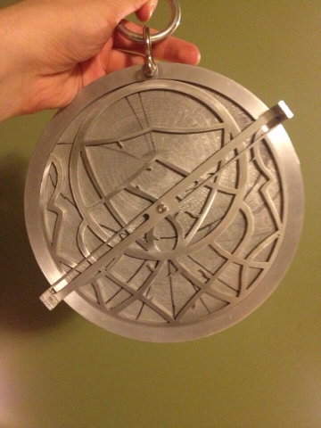
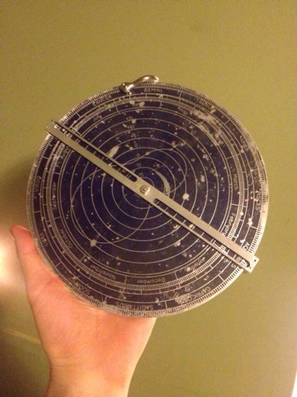
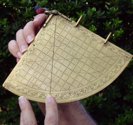
This one is a metal astrolabe. A work in progress that uses some of the output of the Astrolabe Generator.

Astrolabe in progress

Astrolabe in progress

Images used with permission.

Deconstructing the Sine Quadrant-Part 4: The specialized lines – Continued

In Part Three we examined the obliqity arc and how to use it to find the local angle of the Sun at Noon. This week we are going to look at one use for that information, and in doing so, examine another of the sine quadrant’s advanced functions.

Links
The previous installments in this series can be found here:
Part One
Part Two
Part Three
Printable example Sine Quadrant

Sine Quadrant

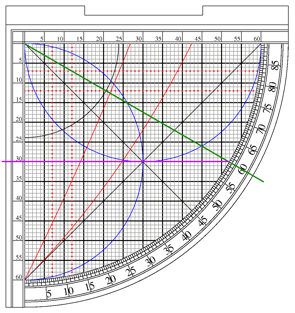
The Asr Lines
One of the major uses of the sine quadrant was computing the proper times for the Muslum mid-afternoon prayer, Asr[1]. To make this task easier, there are often special lines cut into the face of the quadrant.

Prayer Times
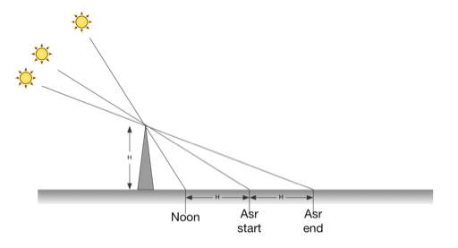
Traditionally, the times set for the 5 daily prayers required by the Muslim religion are based on the Sun’s position in the sky[2]. Of interest to us today is the mid-afternoon prayer, Asr. The period for Asr begins when the shadow of a vertical pole is equal to its noontime length plus the length of the pole; and ends when the shadow is the noontime length plus twice the length of the pole.[3]

Shadows.png

Because Asr is based on the Sun’s shadow, the times will vary depending on location, and determining the proper times for prayer must be done for each day. The sine quadrant allows the user to determine these times accurately and quickly.

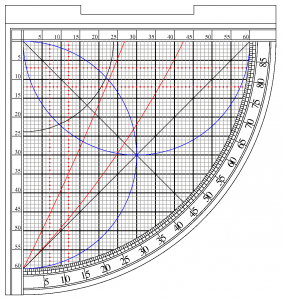
If you look at the example quadrant, you will see a pair of shallow (almost straight) diagonal curves, marked in red. The curves run from the zero degree mark up to roughly the middle of the horizontal scale. The lower line is used to compute the start of Asr, the upper (often missing) allows you to compute the time for the end.

By the definition above, both times are based on the Sun’s position at Noon; This gives us one use for finding the Sun’s noontime altiude. Once the angle of the Sun at local Noon is found, it is just a matter of marking where that line crosses the two Asr curves, to determine the Sun’s angle at the beginning and end of Asr.

For example: Let’s work through finding the times for Asr for 31 degrees North (just south of the city of Alexandria, Egypt), for the 15th of February. If needed, you can go back and review [part 3] concerning the use of the obliqity arc.

First, determine the Sun’s angle at Noon:
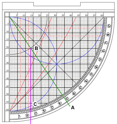
The 15th of February is 56 days after the Winter Solstice on December 21. So, remembering that the solstices are at the 90 degree mark of the angle scale, we count down 56 degrees and place the cord at 34 degrees (A). Make a note of where the cord crosses the obliqity arc (B), and follow that point down to get an angle of 13 degrees(C).

Finding noon with a sine quadrant

Remember that this is Winter, so the Sun is in the South and therefore the declination is negative, giving us a solar declination of -13 degrees. Using that and our known latitude we compute the Sun’s angle at noon to be:

(90-31) + -13 = 46

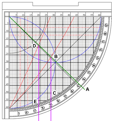
Now that we know what the Sun’s angle at Noon will be, we can determine its angle for the beginning and end of Asr very easily using the Asr lines: Place the cord on the computed Noon angle(A), and note where the cord crosses the first Asr line(B); follow this point down to the angle scale to find that the angle of the sun at the start of Asr is 26.75 degrees(C). Now note where the cord crosses the second Asr line(D), and do the same to find the angle of the Sun at the end of Asr to be 18.5 degrees(E).

Finding asr with a sine quadrant

After these two angles are known, it is just a matter of checking the Sun’s altitude at regular intervals to know when it is time for the prayer.

In part 5, we will examine another method of determining Asr.

Footnotes:
[1]Bir, Atilla. (2008). Principle and Use of Ottoman Sundials. Retrieved from http://www.muslimheritage.com/topics/default.cfm?ArticleID=942

[2]King, David A. A Survey of Medieval Islamic Shadow Schemes for Simple Time-Reckoning. Oriens, 32(1990), 196-197. http://www.jstor.org/stable/1580631

[3]Note: There are various schools of thought, and regional and cultural variations. The above is not definitive and is based on several sources.

An Astrolabe in Work

I got this last night via Twitter:

An astrolabe being assembled

https://twitter.com/cforchino/status/434176137216794626

Nice work, he has a steadier hand than I do. Please do email or tweet me your astrolabes, I’ll be glad to post them. Addresses are on the right.


Deconstructing the Sine Quadrant-Part 3: The Advanced Functions Continued

In part two we began examining the functionality provided by the various lines and arcs visible on the front of a typical sine quadrant. The use of the sine and cosine arcs was fairly straight-forward, being related to the basic function of the device (converting from angle to sine/cosine and back). Next we are going to examine one of the more complex functions; one that will be very useful in later installments.

Links
The previous installments in this series can be found here:
Part One
Part Two
Printable PDF of the example Sine Quadrant


Sine_Quadrant.PNG

The Obliquity Arc
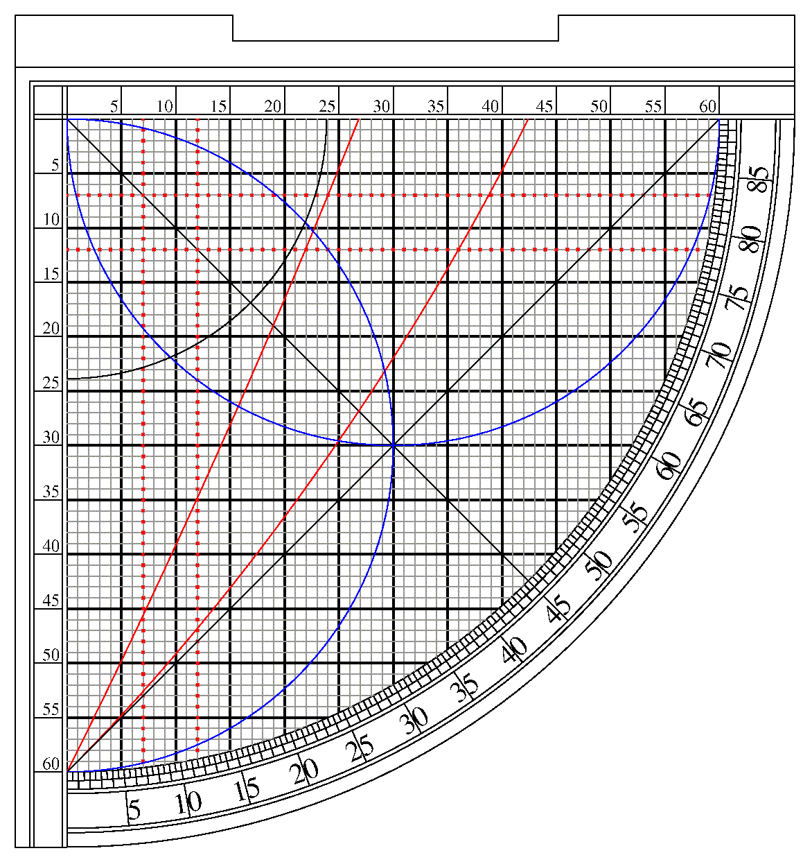
Another line found on many examples of the Sine Quadrant is a circular arc centered on the origin point at the quadrant’s right angle. With a radius of approximately 24 units (marked in black on the figure above) this arc is a projection of the Earth’s orbital obliquity (tilt). The purpose of this marking is to allow the user determine the Sun’s declination (angle above or below the equator) for any given day, allowing the user to then determine the sun’s altitude at noon for that day(besides being neat, this will be of use later on: See part four.)

To understand how this works we will need to review a bit of basic astronomy:

The Earth’s axis of spin, and therefore its equator, is tipped 23.4 degrees to the plane of the planet’s orbit.
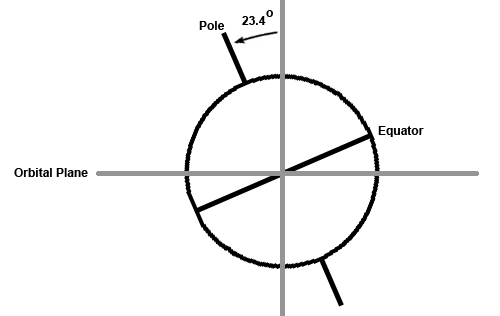
This means that as the Earth moves around the Sun in the course of a year, the Sun appears to move back and forth over the equator spending time in both the Northern and Southern hemispheres.

Traditionally, the Sun’s path through the sky (the ecliptic) is divided up into 12 30-degree zodiac signs. The Spring Equinox defines the zodiac’s starting point, the “First Point of Aries” (Aries 0), when the sun is directly over the equator getting ready to head north. At this point the day and night are of equal length. Each day the Sun moves a little way along the ecliptic, progressing through the zodiac signs until it returns to its starting place. As the days pass the Sun appears to creep north until the Summer Solstice, when the Sun is at its northern-most point and the day is at its longest. Then the Sun moves back south. The movement of the Sun and the seasons should be familiar to all.

Now look at the following diagram:
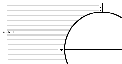
At the equinox the sun appears directly above the equator, so for someone standing on the equator, at noon the sun would be directly overhead, at an angle of 90 degrees to the horizon. If another person was standing at the North Pole at the same time, they would see the Sun on the horizon, or at 0 degrees elevation. Therefore, you can compute the angle of the Sun above the horizon for the equinox as:

noonAngle = 90 – lat

When the Sun is at a different part of the ecliptic, it will be up to several degrees north or south of the equator, so the equation becomes:

noonAngle = (90 – lat) + DecSun

Or to put it another way, you can compute the Sun’s noon altitude if you subtract your latitude from 90 and then add the Sun’s declination for that day.

Example: Given you are at 50 degrees north latitude, find the Sun’s noon altitude for the Summer and Winter solstices:

Summer: (90-50) + 23.4 = 63.4 degrees
Winter: (90-50) + -23.4 = 16.6 degrees (remember the Sun has a negative declination in winter/south of the equator)

Returning to our sine quadrant now: How can we determine the Sun’s declination for a given day?

The zodiac is divided up into 360 degrees. Think about it this way: At the Spring Equinox the Sun is 0 degrees on the zodiac; at the Summer Solstice the Sun is at 90 degrees; at the Fall Equinox, 180 degrees; Winter Solstice sees the Sun reach 270 degrees and finally returns to 0 at Spring Equinox again.

Now take the sine quadrant and hold the cord at 0 degrees. Note where it crosses the obliquity line and follow the grid down and read the angle: 0 degrees. Now move the cord to 90 degrees and do the same: you will get an angle of about 23.5 degrees.
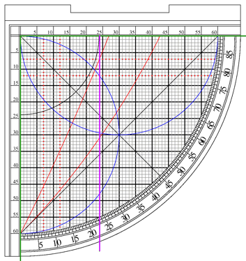
Finding the declination


At this point reverse the direction you move the cord and move an additional 90 degrees to 180 (the cord is now back at 0). By moving the cord up and back four times you sweep out 360 degrees, and can simulate traversing the entire zodiac. Zero degrees represents the Spring and Fall equinoxes, and 90 degrees represents the Summer and Winter solstices.

So, let us say you want to know the angle of the sun at noon for the 5 of May. If you look up the Sun’s position for that date in your ephemeris (if you needed to use this device you would most likely have one hanging around), you get a figure of Taurus 15. Taurus is the 2nd symbol in the zodiac, so add 15 to 30; this gives us 45 degrees. Move the cord to the proper position, 45 degrees, and mark where it crosses the obliquity arc, follow this point down to the degree scale and read off the Sun’s declination as 16.5. You are still standing at 50 North (from the previous example), so you can compute the Sun’s elevation at noon for that day to be:

(90-50) + 16.5 = 56.5 degrees

So, what if you misplace your ephemeris? Then what? Well, there are 365.25 days in a year, and 360 degrees in a circle. Counting one day per degree only puts us off 5.25 degrees by the end of the year, this would translate to an error in declination of less than two degrees. If we are counting days since the last solstice or equinox, the possible error is only a quarter of that, probably within the observational error of the instrument. So, depending on how important fine accuracy is to you, you might not need an ephemeris at all.

Let’s rework the last example without an ephemeris:
The Spring Equinox is March 20th, therefore the 5 of May is 46 days later. So moving 46 degrees around from 0 (Spring Equinox) we place the cord at 46 and read a declination of 17 for the Sun. This is only slightly off (half a degree) from the figure we got above (16.5).

So. as we have seen, with a little mental calculation, a person can use a sine quadrant to find the angle of the Sun at noon for any day of the year. The obvious next question is why would you need to know? Next week I will be explaining that, and discussing some more of the functions of the sine quadrant.
 

Deconstructing the Sine Quadrant-Part 2: The Advanced Functions

In the previous post, I described the basic features of the Sine Quadrant, and described two of its most common functions: measuring angles and converting back and forth from angle to sine/cosine.

[If you need it, here is a link to the PDF of the example sine quadrant you can print out to follow along.]

In this and subsequent posts I will start to dig deeper, and examine the function of some of the other markings on the face of a typical sine quadrant.

The reader is now familiar with the sine/cosine grid and its uses, but a close examination of the face of our example sine quadrant shows several lines and arcs we have not yet discussed.

Sine_Quadrant.PNG

The Sine and Cosine Arcs
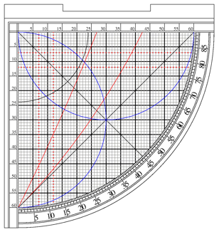
On many sine quadrants there will be two half-circle arcs (blue on the figure above), one centered on the Sine scale, one centered on the Cosine scale. These can be used in conjuction with the Sine and Cosine scales as an alternative method of converting angles to sine/cosine.

Note: If these arcs are to be used, there has to be a moveable bead on the weighted cord, this bead is used as a cursor to mark a position on the cord. Think of it as memory storage for the device.
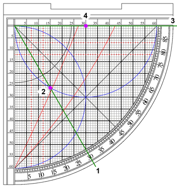
To use these arcs, the procedure is similar to using the grid. First the user pulls the cord taught over the desired angle. Next, the user slides the index bead to rest directly on the appropriate arc (the horizontal arc for sine, the vertical for cosine). Once the marker is in place, the user will then rotate the cord to the sine or cosine scale and read the answer from the point under the bead.

In the figure below the cord is first set to 30 degrees(1), the bead is then positioned directly on the sine arc(2), then the cord is rotated to the horizontal sine scale(3) and the sine is read(4) as 30/60 or 0.5.

Converting to other way, from sin/cosine back to an angle is straightforward as well the user just lines the cord up with the scale, positions the bead at the given sine or cosine; then rotates the cord until the bead touches the appropriate arc. Then the cord will be set to the equivalent angle.


Deconstructing the Sine Quadrant-Part 1: Introduction

The development of mathematics and the sciences through-out the medieval period spawned a range of clever, elegant tools for observation and computation. Devices such as the Armillary Sphere and the Astrolabe are familiar sights in the art of both Europe and the Middle East; but lesser known are a class of tools known as quadrants.

Quadrants come in several different varieties, each with their own uses. Astrolabe Quadrants “fold up” the lines and scales of an astrolabe into a compact device that can perform most of the same calculations. Horary Quadrants deal with telling time and converting between differing time keeping systems. The subject I will be discussing in this current series is a third type, the Sine Quadrant, also known as a Sinecal or Rubul Mujayyab, a device that allows the user to perform quick, accurate trigonometric calculations, along with several other related functions.

Sine Quadrant

(Here [SineQuadrant.pdf] is a link to a PDF of a typical sine quadrant that you can print out and use to follow the discussion)

The Basic Features:
Most quadrants are shaped, logically enough, as a quarter-circle, with two straight sides meeting at a right angle and a quarter-circle arc closing the open end (A).

Major parts

The Angle Scale
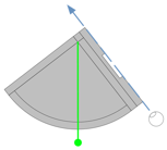
Along the curved side is a scale marked off in 90 degrees, usually grouped into five degree sections. Used with the sights and a weighted cord (see below), the user can sight on a target and determine the angle of elevation by seeing where the weighted cord lies on the angle scale (B).

The Horizontal and Vertical Scales
Along each straight edge of the sine quadrant is a scale. These are traditionally divided into 60 units and subdivided into 12 five-unit sections. This base-60 (or sexagesimal) numbering is a hold-over from the ancient Babylonian number system that still survives in our divisions of time and angles. The horizontal scale is used for computing the Sine of an angle, the vertical scale is used to compute the Cosine of an angle (C).

The Cord
At the right-angle of the quadrant there is a small hole from which hangs a weighted cord. This cord is used as an index line when doing calculations. It also works as a plumb line when the quadrant is used to measure altitudes.

The Sights
On most quadrants there is also a set of sights. Sometimes these are sighting vanes with holes for sighting through; sometimes a square notch is cut out of one side, providing two posts that can be sighted across (D).

The Sine/Cosine Grid
On the face of the sine quadrant there is a grid (60 by 60) matching the horizontal and vertical scales dicussed above. As on the scales, every fifth line is often set apart, either by width or with special markings.

Sine Quadrant

Measuring angles
The most basic function of the Sine Quadrant, common to all quadrants, is measuring angles. By using the sights, the weighted cord, and the angle scale together, a user can determine a vertical angle with a good amount of accuracy.

Sighting

Finding the Sine and Cosine of an Angle
It is often necessary to find the Sine or Cosine of an angle when performing a calculation. Finding the rough figure for Sine or Cosine given an angle is easy using a Sine Quadrant.

For example: Given the angle of 30 degrees, find the sine.
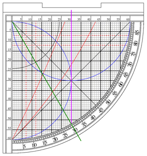
— Holding the quadrant, move the cord until it is held taught on the 30 degree mark (Green line).
— Next look at the point that the cord crosses the curved edge do the grid.
— Follow that point vertically until you reach the horizontal sine scale and read the result (Purple Line). An angle of 30 degrees gives us the correct sine of 30/60 or 0.5.

Finding sine

Computing Cosine is done in a similar manner. Notice that as the cord is rotated from 0 to 90 degrees the sine varies from 0/60 (0) to 60/60 (1) with the Cosine changing in reverse from 1 to 0, as expected.

Finding cosine

To find the angle represented by a sine, the process works in reverse: Given a sine of .5 or 30/60, trace the 30 line down to the rim of the grid, place the cord there and read the angle.

In the next post I will dig into some of those advanced lines and functions you can see on the face of the sine quadrant.


Sources:
Top photo: Gerry Young, released under Creative Commons Attribution Share-alike 3.0 license (http://en.wikipedia.org/wiki/File:Taking_the_Measure.JPG

Pennsic War 42 Followup

(Ok, so I’m a bit late with my essay “What I did on My Summer Vacation”, sue me.)

I committed to three activities related to this project this past Pennsic: Firstly, I taught a pair of two-hour sessions of my class “The Astrolabe in Theory and Practice” at Pennsic University. In addition I displayed my research and astrolabe examples at the Pennsic Arts and Sciences display. Finally I organized a “Scientific Instruments Day” to run as part of the Pennsic U. Artisan’s Row.

Pennsic will require some explanation to those who do not know what I’m talking about. The Pennsic War is the largest annual gathering of members of the Society for Creative Anachronism (SCA). Every year around the end of July/beginning of August a massive tent city appears in western Pennsylvania. Upwards of ten thousand medieval re-creationists from all over the world gather for two weeks away from the twenty-first century. There are tournaments, battles, parties, shopping and quite a bit of very good music. In addition, Pennsic “University” hosts close to a thousand class sessions with volunteer teachers giving instruction on a bewildering range of subjects. In recent years, the university has added a feature called “Artisan’s Row”, where tents are set aside for all-day displays and demonstrations of various arts and sciences.

Both my class sessions went very well, and were very well attended. As usual, I met a wide range of interesting people. This year included a pair of students and their professor, who I had a lot of fun interacting with. My plans for classes for the coming year are in flux at the moment; but I will teach at least one astrolabe class. I am hoping to add a new class, concerning quadrants, but the scope and content are still being worked on. In addition, I would really like to do a class on using the astrolabe to cast a astrological chart using medieval techniques (I have references), but as it would require the students to be familiar with the astrolabe as a prerequisite, I don’t see it happening at Pennsic U. I might set up a live demonstration at the Arts and Sciences display, however.

Arts display

The Arts and Sciences display at Pennsic this year was, as usual, excellent. I talked to dozens of interested people, and made some good contacts. In addition to my display, there was also a gentleman, Master Johannes, displaying his own work a new translation from Latin of Christanus of Prachatice (1410) – instructions for constructing an astrolabe.

Finally, this year I was able to get my act together and actually make “Scientific Instrument Day” happen. In addition to displaying and discussing my own work, several other researchers and instrument makers participated. My friend Rhonwen ferch Tudor (as she is known in the SCA), loaned me the stained glass sundial she made last year, inspired by the wonderful and functional medieval stained glass sundials that can still be seen in parts of Europe. Adam Coulson came to display and discuss his hand-made clock. Each part hand-crafted, it was amazing to watch it working. Master Johannes displayed his translation project and several other artisans also displayed. There was a steady stream of visitors all day. The day was such a success that I hope to do it next year as well.

What I’ve been up to

Wow, how time flies. It is almost a year since I last posted here. 

New Years Resolution: Post at least once a week. Yeah, let’s see how long That One lasts…

Not that I’ve been idle. In the intervening months I have gotten quite a bit done, I just haven’t been sharing. Since my last entry I’ve accomplished  the following:

Updates to the Astrolabe Generator:

  • Added support for extreme latitudes. The generator now will handle 90S to 90N.
  • Finally added support for labeling the astrolabe with Zodiac symbols.
  • Numerous bug fixes and tweaks.

The next version of the Astrolabe Generator:

  • Conversion to Java is proceeding. All the functionality of the current version is up and running; only the user interface is still needing work. This version will (hopefully) be web-based AND downloadable to your local machine.

Side projects:

  • I’ve gotten seriously sidetracked into researching a related class of instruments, the quadrants, most specifically Sine Quadrants (Rubul Mujayyab). More about that project in a later post.

Teaching:

  • This past summer I once again taught two well-attended classes at Pennsic War. I am hoping to teach an advanced class this coming year, but plans are still evolving.
  • Scientific Instrument Day: This year I tried something new and hosted an all-day display/discussion session at Pennsic University’s Artisan’s Row. Scientific Instrument day was well attended and had several interesting displays. More on that later as well

Construction:

  • Over the last few months I’ve been getting involved with a local Maker group: NOVA Labs. This will give me access to a full wood and metal shop, as well as an industrial laser cutter. I hope to be able to build astrolabes and quadrants in something other than paper soon.

Research:

  • Lots of research into the underlying math of the astrolabe and the quadrant.
Keep checking back for more information. I promise more updates to come.

The Astrolabe as an Artist’s Tool

In this week’s email:

“I use your astrolabe constantly for my artwork, I make extremely long exposure pinhole photographs tracing the suns path over the course of a day to half a year. www.matthewallred.com 

I use your astrolabe to determine rise / set times and declination as well as the transit alt for the sun. Then plan which time of the year a given location will look best. It is absolutely a joy to work with an astrolabe in the field. Sure I could do the same thing with my iphone but I don’t feel like it is in the spirit of pinhole photography. “

I maintain this site as a place to organize my work, I is good to know that there are people out there finding it useful as well.

Major Update!

Yeah, I’m still plugging away, between burnout and other commitments I haven’t had a lot of time for this project. This has changed with the turning of the year.

First up, I have made a major update to the Astrolabe Generator. I finally figured out a way to digitize a set of zodiac symbols and set them up for scaling and inserting into the EPS files. The code is working well; and so there is now an option to label the zodiac on the back and the rete with symbols instead of text. In addition the arcs of the signs and the lunar mansions scales are now properly labeled.  I also added an option to change the astrolabe shape to an octagon, both for look and to make it easier to cut out.

Next, I’m starting to prepare for the classes I want to teach this year at the Pennsic War. This involves major work on the astrolabe manual, I’m hoping to have chapters to post soon.

Finally, the drafting project has not been abandoned. I hope to get the plates done over the next six months.