Drafting the Astrolabe 4: The Front
- on 10.30.11
- Astrolabe Project, Drafting The Astrolabe
- No Comments
Back to work on this project:
I got several tasks done today.
When I am finished drafting my astrolabe, I plan on photocopying it onto card stock, and assembling and laminating it in order to compare it’s accuracy to a computer-generated version. I tested the photocopy process today.
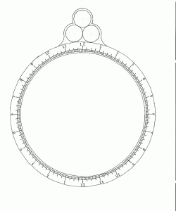
First, I printed out the front of the computer-generated version of the astrolabe and then photocopied the printout. Then I measured the two with my point-scaled ruler (Note: PostScript measures in points: 1/72 of an inch).
The printed out version is a uniform 503 points in diameter, horizontally, vertically and obliquely (45 degrees). The photocopied version is 501 points horizontally and vertically, and 504(!) obliquely. Obviously my home photocopier is distorting the image a bit. If the hand-drawn version is going to be distorted for testing, it will skew the results.
Two possible options suggest themselves:
1. Test other, commercial, photocopiers for distortion an see if I can use them instead.
2. For testing, photocopy the computer generated version as well. If the distortion is uniform, as I suspect it will be, it will be the same for both test and control.
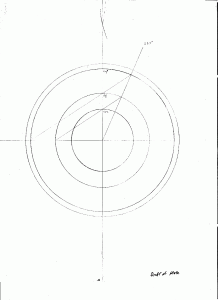
Next I got out the drawing tools and drew up a template for the climate plates. The three tropic rings will be the same for each plate, so constructing them each time is a waste of effort. The compass can instead be set from the template and the rings transferred to the individual climate sheets.
Next. I drafted up the front of the mater. First I drew a line down the center of the paper. then erected an perpendicular bisecting line using Method 1. I then transferred the lines for the inner and out edges of the mater limb from the printout of the computer generated example, to the paper using the compass. Four additional circles were drawn between these two circles to mark the various lengths of tick marks for the time scale.
The limb is to be marked in hours, half hours, quarter hours and five-minute ticks. To accomplish this I then used Method 6 to trisect the 4 quadrants, dividing the limb into 12 two-hour sections. I then bisected (Method 5) the angles giving me 24 one-hour sections. These 24 sections I marked across all four scale lines. I then again bisected the hour angles into half hours, and marked these across 3 rings. Bisecting again gave me my quarter-hour lines. marked over two rings.
Finally I abandoned the compass and straight-edge and eyeballed the division of the quarter=hour sections into three 5-minute sections (marked over two lines). I cleaned up the result by erasing most of the construction lines; and I inked the result carefully with a 0.1 mm drafting pen.

