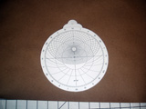
Constructing an Astrolabe
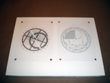
There are two ways to approach this. What I refer to as the “Desktop Model” and the “Hand-held Model” The desktop version mounts the parts of the astrolabe on a square of foam board, with the front and back of the astrolabe side by side. This is the easiest way of constructing it, and allows you to swap out plates simply to play with variations
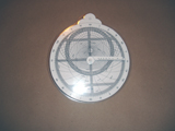
The hand-held model is much cooler, but less flexible. This looks like an actual astrolabe, but requires careful assembly and lamination.
Requirements:
- The .zip archive created by the Astrolabe Generator, or the demo archive (demoastrolabe.zip) if you wish to work the problems on the website.
- Software and a printer for printing out EPS files. See below under Software (NOTE: Your local print shop might be able to do this)
- 8 1/2 by 11 Cardstock (3 sheets per astrolabe), color of your choosing (I prefer white)
- 8 1/2 by 11 Transparency film (1 sheet per astrolabe)
- Several flat-headed thumbtacks and a stiff, sharp pin
- Scissors
If you are building the desktop version you will also need:
- Additional thumbtacks
- 1/2 inch Foam board or similar for mounting
If you are building a hand-held version you will also need:
- A fragment of pencil eraser or an earring back.
- Spray mount
- 2 letter sized 5 mil heat lamination pouches
- 1 letter sized 3 mil heat lamination pouch (optional)
- Access to a heat laminator.
(NOTE: The envelopes and the laminator are probably available at your local print shop)
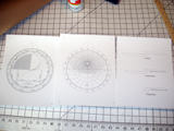
[photo of the two requirement sets]
The Desktop Model:
- Unzip the archive using your usual method.
- Print out FRONT.EPS, BACK.EPS and RULES.EPS on card-stock.
- Print out RETE.EPS on transparency film.[photo]
- Carefully cut out the alidade and your choice of rule (double or single).
- Cut out the rete.
- Cut a rectangle of foam board to a size to comfortably hold the front and back sheets(say 14 inches by 21 inches).
- Tack the front and back sheets to the foam board
- Use a stiff sharp pin to CAREFULLY pierce pilot holes in:
- The exact center (Where the N/S and E/W lines cross) of the front and back views
- The exact center of the rete (marked with a cross)
- The pivot point of the alidade and rule (marked with a cross)
- Using the pilot holes made above, press a thumbtack through the pivot of the rule, then through the center of the rete and finally press the assembly into the center of the front view.
- Again, using the pilot holes, press a thumbtack through the pivot of the alidade and press the assembly into the center of the back view.
Your desktop astrolabe is now ready to use!
The Handheld Model:
(NOTE: you will want to do this in a well ventilated area, and put down some newspaper or other covering to protect the surfaces you are working on. Spray mount overspray is a pain)
- Unzip the archive using your usual method.
- Print out FRONT.EPS, BACK.EPS and RULES.EPS on cardstock.
- Print out RETE.EPS on transparency film.
- Use a stiff sharp pin to CAREFULLY pierce the exact centers of the registration marks in the top corners of the Front and Back views.
- CAREFULLY press a thumbtack through each of the holes you made in the back view and place it face down (the points of the tacks should be up)
- CAREFULLY press the front view, face up, onto the tacks, using the pilot holes. the two sheets should be back-to-back
- Being careful not to pull the front off the tacks, lift up the free end and spray a light coat of spray mount on the back view. [photo]
- Carefully smooth down the front onto the back and give the glue time to dry.
- Remove the tacks and cut out the assembled astrolabe body.
- At this point test the alignment of the astrolabe front and back by carefully pushing a sharp, stiff pin through the exact center of the front, and seeing how close to center the hole is on the other side. The exit hole should touch the center cross. If it is not properly centered, Repeat steps 1-9 taking better care with alignment. [Photo]
- Laminate the parts as follows:
- Place the astrolabe body in a 5 mil laminating pouch and run it through the laminator at least twice, once on each side. do this until it lays flat.
- Place the rule sheet in a 5 mil laminating pouch and run it through the laminator.
- Optional: Place the rete in a 3 mil laminating pouch and run it through the laminator. This will make the printing on the rete much more durable, and stiffen the rete [photo]
- Cut out the astrolabe body. Note that you want to cut outside the edge of the astrolabe, leaving at least 1/8 inch of the lamination sealed.
- Cut out the rules and alidade, being careful to cut directly on the lines
- Cut out the rete [photo]
- Use a stiff sharp pin to CAREFULLY pierce pilot holes in:
- The exact center (Where the N/S and E/W lines cross) of the astrolabe body
- The exact center of the rete (marked with a cross)
- The pivot point of the alidade and rule (marked with a cross)
- Using the pilot holes, press a thumbtack through the pivot of the alidade and then press the assembly through the center of the astrolabe body back. [photo]
- On the front of the astrolabe, place the rete on the exposed tack point. Then place the rule with the tack through the pivot point. [photo]
- Cover the exposed tack point with a piece of eraser, or an earring back. [photo]
Your desktop astrolabe is now ready to use!
(NOTE: In his book, Morrison recommends using small nylon screws for the pivot. I have tried this, but it is very difficult to drill clean holes of accurate size, accurately placed, in 4 different parts, and have everything line up accurately. I hit on the thumbtack idea and it works much better for me. If you wish to use a screw, use a #35 (0.110 inch) drill bit and a #4-40 pan head nylon screw and self-locking nut)
Software:
The Astrolabe Generator provides the user with a .zip archive containing a series of EPS(encapsulated PostScript) files that need to be printed out. To do this you will need a laser printer that can handle PostScript, and software that will allow you to view and print the files:
Viewing/printing EPS files:
Windows, OS2, Linux
GSView and GhostScript: http://pages.cs.wisc.edu/~ghost/gsview/index.htm
Printing EPS files:
Windows
PrintFile: http://www.lerup.com/printfile/
